Designing a fire alarm system is a complex process that requires precision, compliance, and careful coordination with other building systems. Among the most critical integrations in modern design workflows is the connection between fire alarm layouts and electrical schematics. Combining these two elements ensures that fire alarm systems function reliably, circuits are correctly configured, and installations meet both safety codes and operational requirements. Advanced Fire Alarm Design Tools like those offered by XTEN-AV make this integration seamless, improving accuracy, efficiency, and collaboration across project teams.
Introduction to Fire Alarm and Electrical System Integration
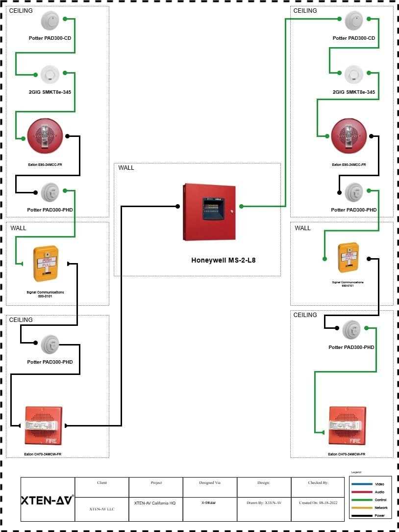
Fire alarm systems rely heavily on electrical infrastructure to operate. Detectors, manual pull stations, notification devices, and control panels all require power and communication circuits. Misalignment between the fire alarm layout and electrical schematics can lead to installation delays, faulty devices, or system failures.
Integrating Fire Alarm Design Tools with electrical schematics ensures that every device is not only properly placed but also correctly powered and connected. This integration facilitates loop design, load calculations, and circuit validation, which are essential for NFPA 72 compliance and overall system reliability.
In large projects, such as hospitals, commercial complexes, and high-rise buildings, the need for coordination becomes even more critical. Electrical engineers, fire protection engineers, and AV consultants must collaborate closely to prevent conflicts between systems and guarantee operational efficiency.
Understanding Fire Alarm Design Tools
Fire Alarm Design Tools are specialized software platforms that allow engineers to plan, visualize, and verify fire alarm systems. They provide capabilities such as device placement, loop design, coverage mapping, and compliance verification.
Modern tools often integrate CAD-based interfaces, allowing layouts to align perfectly with architectural drawings. They also support advanced features like automatic detector spacing, intelligent zoning, and real-time compliance checks against NFPA standards.
When paired with electrical schematic software, these design tools enable engineers to overlay circuits, verify power supply adequacy, and detect potential conflicts between systems before construction begins.
Benefits of Integration
Integrating fire alarm design with electrical schematics provides multiple benefits:
Accuracy – Designers can ensure that every detector, alarm, and notification device is properly powered and connected.
Compliance – Integrated systems simplify adherence to NFPA 72, local electrical codes, and building standards.
Efficiency – Engineers can identify and resolve circuit conflicts early, reducing rework during installation.
Documentation – Combined layouts and schematics provide comprehensive records for approvals, inspections, and future maintenance.
Collaboration – Electrical and fire safety teams can work simultaneously on a shared platform, improving communication and coordination.
Step 1: Import Architectural and Electrical Drawings
The integration process begins with importing architectural plans and electrical schematics into your Fire Alarm Design Tools. Most modern platforms support DWG, DXF, and PDF formats, allowing seamless transfer of data from other design software.
Importing architectural layouts ensures that fire alarm devices are placed accurately relative to walls, corridors, and exits. Electrical schematics provide critical information about power sources, circuit routing, and breaker capacity. By overlaying these drawings, engineers can visualize how the fire alarm system interacts with the building’s electrical infrastructure.
Step 2: Define Zones and Circuits
Once the base drawings are in place, the next step is to define fire alarm zones and circuits. Zones represent areas of coverage, while circuits determine how devices are electrically connected.
Fire Alarm Design Tools allow engineers to map loops and circuits while automatically checking for voltage drop, maximum device counts, and cable length limitations. Integration with electrical schematics ensures that each loop has adequate power and is properly routed through distribution panels, minimizing the risk of overloads or underpowered devices.
Step 3: Device Placement and Circuit Assignment
With zones defined, engineers can begin placing fire alarm devices. Modern tools offer libraries of detectors, manual stations, strobes, and notification devices. Each device can be assigned to a specific circuit, and the software can simulate how the electrical load affects performance.
Integration with electrical schematics allows engineers to verify that:
Each device receives the required voltage.
Power supplies are sufficient for total device load.
Backup batteries and emergency circuits are properly connected.
Notification devices are coordinated with the electrical system for proper synchronization.
This step reduces the likelihood of installation errors and ensures that fire alarm devices operate reliably under normal and emergency conditions.
Step 4: Automated Compliance Verification
One of the key advantages of modern Fire Alarm Design Tools is automated compliance verification. As devices are placed and circuits mapped, the software checks spacing, coverage, and electrical connections against NFPA 72 and local codes.
When integrated with electrical schematics, the software can flag:
Circuit overloads
Voltage drops beyond permissible limits
Incorrect wiring or loop topology
Missing connections between critical devices and power sources
This proactive validation prevents costly rework and helps engineers produce designs that pass inspection on the first submission.
Step 5: Generate Documentation
After the design is complete, Fire Alarm Design Tools generate comprehensive documentation that combines layout drawings and electrical schematics. Reports typically include:
Device lists with specifications and quantities
Loop and circuit diagrams with load calculations
Zone coverage maps
Compliance reports referencing NFPA and electrical codes
Having integrated documentation simplifies communication with contractors, inspectors, and project stakeholders. It also provides a clear record for future maintenance or system expansion.
Step 6: Collaboration and Cloud Integration
Integration extends beyond software interoperability. Modern Fire Alarm Design Tools often include cloud-based collaboration features, allowing multiple team members to work on the same project simultaneously.
Electrical engineers can update schematics while fire alarm designers adjust device placement, with real-time updates visible to all team members. Version control ensures that changes are tracked, reducing errors and improving accountability.
Step 7: Simulation and Testing
Some advanced platforms also support simulation of electrical circuits and fire alarm responses. Engineers can test how devices will behave under emergency conditions, verify synchronization of notification devices, and simulate power interruptions.
These simulations provide an additional layer of validation before installation, helping to ensure that the integrated system functions reliably in real-world conditions.
Best Practices for Integration
Standardize Layer Naming – Consistent layer names improve clarity when importing and overlaying drawings.
Maintain Accurate Scale – Correct scaling ensures that both fire alarm devices and electrical circuits are properly aligned.
Use Template Libraries – Predefined device libraries and circuit templates reduce design time and improve accuracy.
Coordinate Early – Involve electrical engineers and fire safety professionals early in the design phase to avoid conflicts.
Document Everything – Generate comprehensive reports that combine layout and electrical information for inspection and maintenance purposes.
Conclusion
Integrating Fire Alarm Design Tools with electrical schematics is no longer optional—it is essential for modern fire protection engineering. By combining layout, device placement, and circuit verification into a single workflow, engineers can ensure system accuracy, NFPA compliance, and operational reliability.
XTEN-AV provides cutting-edge Fire Alarm Design Tools that facilitate this integration, enabling engineers to work efficiently, collaborate seamlessly, and produce high-quality designs that meet the most stringent safety standards. In 2025 and beyond, leveraging integrated design workflows is the key to creating fire alarm systems that are safe, reliable, and fully compliant with electrical and fire codes.
Read more: https://trendverity.com/how-to-use-xten-av-x-draw-to-create-nfpa-compliant-fire-alarm-layouts/